Camera Model
Camera Projection
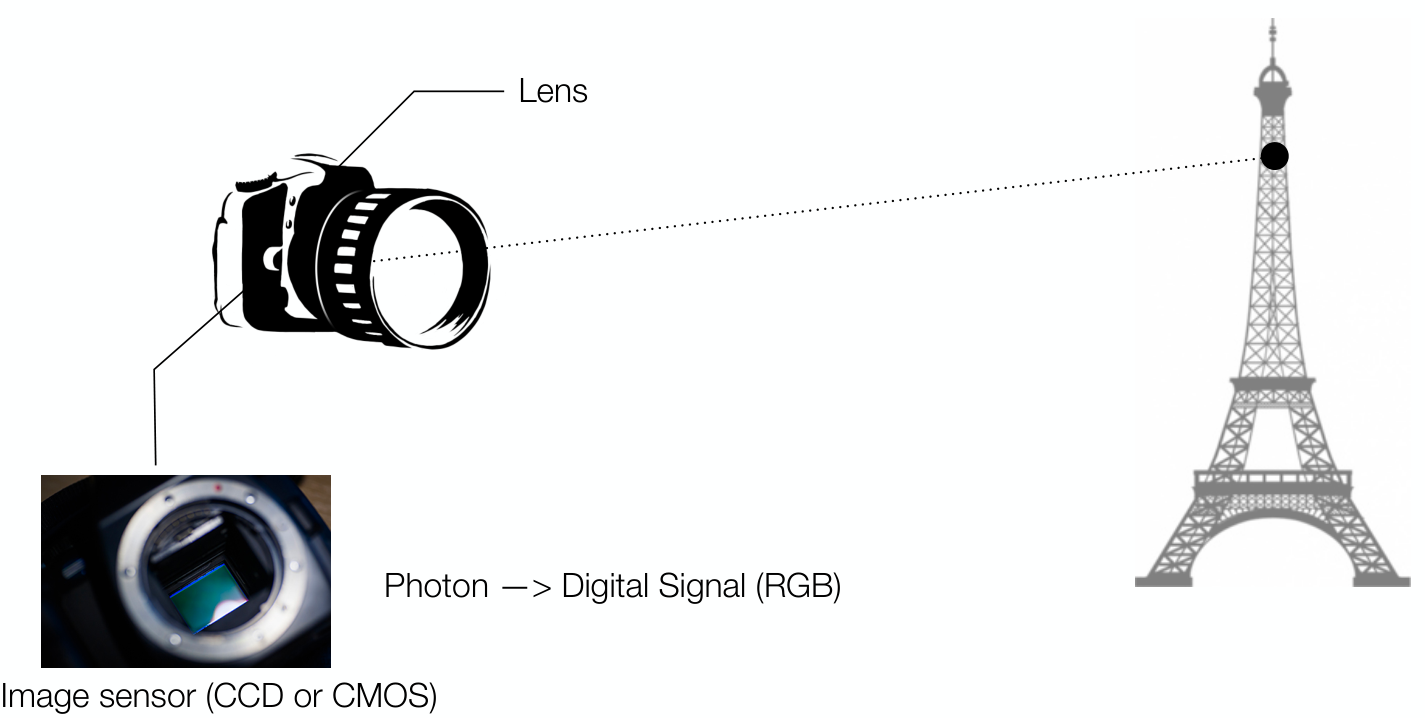
카메라로 현실 세계의 물체를 찍는다고 하자. 이는 다르게 말하면, 현실 세계의 3D object를 카메라를 통해 2D image로 projection한다는 것으로 볼 수 있다.
이러한 camera projection은 다음과 같이 표현할 수 있다 (관련 용어 참조).
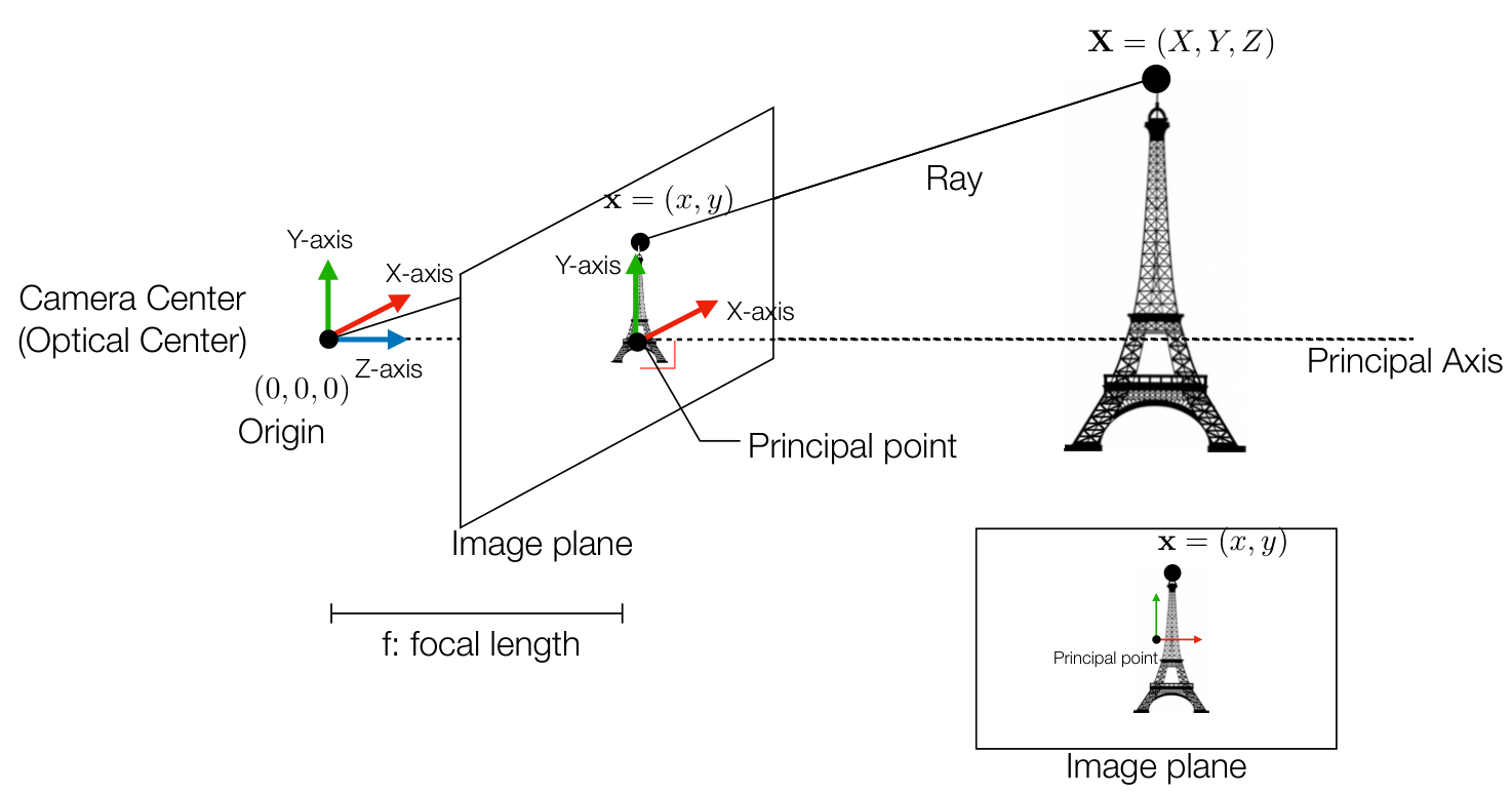
- Focal length: 초점 길이
- Principal axis: camera center로부터 Z-axis로의 ray
- Principal point: principal axis와 image plane이 만나는 지점
Camera Intrinsic Parameters
Obtain 2D Projection
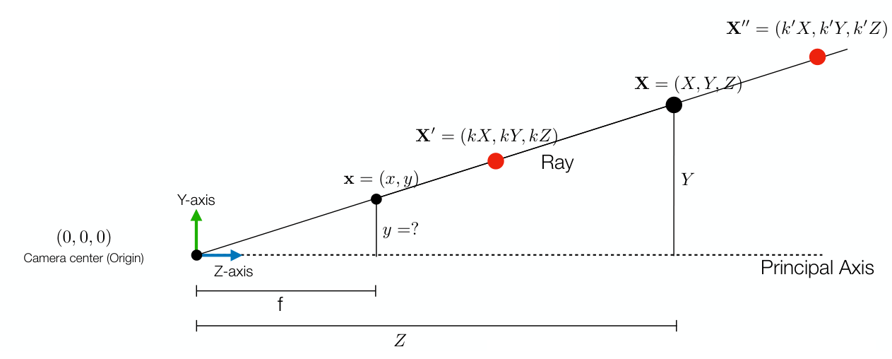
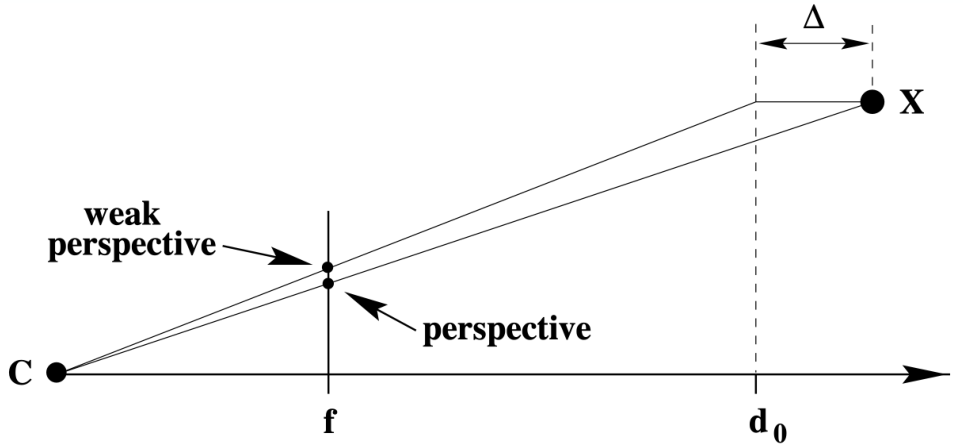
3D object의 point $(X,Y,Z)$를 2d projection의 point $(x,y)$로 바꾸는 것은 기본적으로 삼각형의 닮음 성질을 이용하면 쉽게 얻을 수 있다.
\[\begin{pmatrix} X, Y, Z \end{pmatrix}^T \rightarrow \left( f \frac{X}{Z}, f \frac{Y}{Z} \right)\]특히, 동일한 ray 위의 모든 3D point는 동일한 2D point로 projection 된다.
\[\begin{pmatrix} kX, kY, kZ \end{pmatrix}^T \rightarrow \left( f \frac{X}{Z}, f \frac{Y}{Z} \right)\]Intrinsic and Extrinsic Parameters
앞서 표시한 $\left( f \frac{X}{Z}, f \frac{Y}{Z} \right)$는 inhomogeneous coordinate로 표시한 점이다. 이를 homogeneous coordinate로 표시한다면, 다음과 같이 쓸 수 있다.
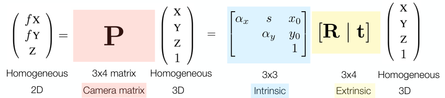
\[\left( f \frac{X}{Z}, f \frac{Y}{Z} \right) \rightarrow \left( fX, fY, Z \right) = \begin{bmatrix} f & & & 0 \\ & f & & 0 \\ & & 1 & 0 \end{bmatrix} \begin{pmatrix} X \\ Y \\ Z \\ 1 \end{pmatrix}\]$\left( fX, fY, Z \right)$는 2D homogeneous이고, $\left( X, Y, Z, 1 \right)$은 3D homogeneous이다.
여기서 \(\begin{bmatrix} f & & & 0 \\ & f & & 0 \\ & & 1 & 0 \end{bmatrix}\)를 camera matrix $P$라고 한다.
Camera matrix는 다음과 같이 분해할 수 있다.
\[\begin{bmatrix} f & & & 0 \\ & f & & 0 \\ & & 1 & 0 \end{bmatrix} \begin{pmatrix} X \\ Y \\ Z \\ 1 \end{pmatrix} =\begin{bmatrix} f & & \\ & f & \\ & & 1 \end{bmatrix} \begin{bmatrix} 1 & & & 0 \\ & 1 & & 0 \\ & & 1 & 0 \end{bmatrix} \begin{pmatrix} X \\ Y \\ Z \\ 1 \end{pmatrix}\]이 때, \(\begin{bmatrix} f & & \\ & f & \\ & & 1 \end{bmatrix}\)을 intrinsic parameter $K$, \(\begin{bmatrix} 1 & & & 0 \\ & 1 & & 0 \\ & & 1 & 0 \end{bmatrix}\)을 extrinsin parameter $[I\mid 0]$라고 한다.
위 식을 다음과 같이 좀 더 간단하게 표현할 수 있다.
\[P\mathbf{X} = K[I\mid 0]\begin{pmatrix} X \\ Y \\ Z \\ 1 \end{pmatrix}\]Origin Changes
앞서 구한 2D image point는 principal point를 (0,0)으로 설정했을 때의 좌표이다. 하지만, 일반적으로는 image plane의 좌하단 corner를 (0,0)으로 설정한다.
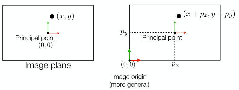
새로운 origin을 기준으로 in/extrinsic parameter를 다시 표현하면 다음과 같다.
\[\begin{aligned} \begin{pmatrix} fX + Zp_x \\ fY + Zp_y \\ Z \end{pmatrix}_{\text{2D}} &= \begin{bmatrix} f & 0 & p_x & 0 \\ 0 & f & p_y & 0 \\ 0 & 0 & 1 & 0 \end{bmatrix}_{\text{Camera Parameter}} \begin{pmatrix} X \\ Y \\ Z \\ 1 \end{pmatrix}_{\text{3D}} \\ &= \begin{bmatrix} f & 0 & p_x \\ 0 & f & p_y \\ 0 & 0 & 1 \end{bmatrix}_{\text{Intrinsic}} \begin{bmatrix} 1 & 0 & 0 & 0 \\ 0 & 1 & 0 & 0 \\ 0 & 0 & 1 & 0 \end{bmatrix}_{\text{Extrinsic}} \begin{pmatrix} X \\ Y \\ Z \\ 1 \end{pmatrix}_{\text{3D}} \end{aligned}\]이 때, $(p_x, p_y)$는 새로운 origin을 기준으로 한 principal point의 좌표이다.
Unit Changes and Non-square Pixels
3D 상의 coordinate은 일반적인 physical unit (mm, cm 등)으로 정해지나, image 상의 coordinate은 pixel 단위로 정해지기에, 이러한 부분에서도 수정이 필요하다. 특히 pixel은 non-square일 가능성이 존재하므로 x-axis와 y-axis에 서로 다른 보정 계수(각각 $m_x, m_y$)가 필요하다.
\[K= \begin{bmatrix} \alpha_x & 0 & x_0 \\ 0 & \alpha_y & y_0 \\ 0 & 0 & 1 \end{bmatrix}\]Origin 변경 시와 마찬가지로 intrinsic parameter만을 변경된다.
여기서, $\alpha_x, \alpha_y$는 각각 $m_xf, m_yf$ 이며, $x_0, y_0$는 각각 pixel unit으로 표현한 $p_x,p_y$ 이다.
매우 드물게, x-axis와 y-axis가 수직이 아닌 경우에는 skew paramter $s$가 필요하다.
\[K= \begin{bmatrix} \alpha_x & s & x_0 \\ 0 & \alpha_y & y_0 \\ 0 & 0 & 1 \end{bmatrix}\]Extrinsic Parameters
앞서 intrinsic parameter에 대해서 분석하였고, 이는 camera 내부에서의 2D image 표시에 관여하는 parameter임을 알 수 있었다.
Extrinsic parameter는 camera 외부의 영향력을 보정하기 위한 계수이다. 지금까지는 우리는 3D의 origin을 특정 camera의 focus로 가정하고 3D coordinate을 계산하였다. 이 때, 만약 하나의 카메라가 더 있다고 가정하자.
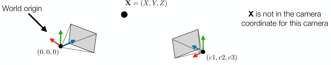
이 경우 3D point $\mathbf{X}=(X,Y,Z)$는 새로운 카메라에 대해서는 기존 카메라와 동일한 camera parameter로는 2D projection을 진행할 수 없다. 따라서, 해당 camera를 위한 coordinate 보정 작업(camera calibration)이 필요하며 이는 다음과 같다.
\[\mathbf{X}_\text{cam} = R\mathbf{X}_\text{world} + \mathbf{t} = \begin{bmatrix} R & \mathbf{t} \end{bmatrix} \begin{bmatrix} \mathbf{X}_{\text{world}} \\ 1 \end{bmatrix}\]특정 camera center를 origin으로 하여 world origin의 위치를 구하면 $-R^T\mathbf{t}$가 된다.
위의 \(\begin{bmatrix} R & \mathbf{t} \end{bmatrix}\)가 새로운 extrinsic parameter가 된다.
일반화 하면, 다음과 같이 표현할 수 있다.
모든 카메라는 각각의 $K, R, t$ parameter를 갖는다.
Affine Camera
Affine mapping은 parallel line을 보존하는 성질을 가지고 있다. Affine camera 역시 그러한 성질을 갖는 camera로, affine camera의 경우 다음과 같은 camera parameter를 갖는다.
\[P_A = \begin{pmatrix} m_{11} & m_{12} & m_{13} & t_{1} \\ m_{21} & m_{22} & m_{23} & t_{2} \\ 0 & 0 & 0 & 1 \end{pmatrix}\]즉, affine camera의 center는 ideal point가 된다.
Direct Linear Transform (DLT)
그렇다면, 어떤 camera의 K, R, t, 또는 P를 어떻게 얻을 수 있을까? 주로 direct linear transform (DLT)과 Zhang’s method가 사용된다. 여기서는 DLT에 대해서만 설명한다.
DLT는 우선, 크기가 알려져 있고 coordinate을 쉽게 찾을 수 있는 object를 이용해 3D와 2d projection pair 정보를 여러개 얻는다.
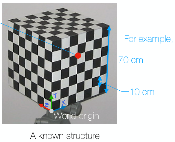
위 그림에서 빨간 점은 3D 상에서 $\mathbf{X_1} = (30, 50, 0)$을 나타내고, image 상에서의 coordinate $\mathbf{x_1}$ 역시 pixel 기준으로 쉽게 알 수 있다.
즉, $\mathbf{x_1} = \mathbf{PX_1}$에서 $\mathbf{x_1}$과 $\mathbf{X_1}$을 알게 된 것이다.
이전 homography를 몇 개의 mapping 정보로 계산해냈던 것과 마찬가지로 (참고), 하나의 mapping 정보로 2개의 식을 얻는다.
Camera parameter는 DoF가 11(up-to-scale로 인해 나머지 1개는 자동 결정)이므로, 최소 6개의 점이 필요하다.
DLT는 3D structure가 정교하지 못하면 error가 커질 수 있다는 단점이 있다.